Installing a Link ECU
Installing your first ECU can feel daunting, but this article aims to demystify the process and break it into easy to achieve chunks.
Having the build mapped out on paper will help you through install and initial setup. This IO (Input/Output) map sets out additional sensor/controller wiring that needs to be done as well as defining which pin is doing what on the ECU, which helps the initial tune configuration.
The following steps work through getting the ECU physically mounted, booted up, and the initial tune configured through to first start. It sets out a workflow to follow, and the more in depth articles go through to explain the concepts behind given settings, rather than advising what numbers to put where.
1. ECU Mounting
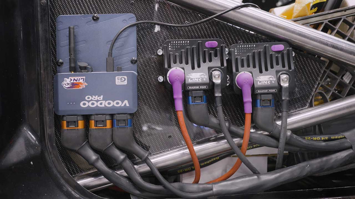
Whether it’s mounted it as a centrepiece on full display, or tucked away in the engine bay, there are some considerations to take with mounting. It’s recommended to mount the ECU in the cabin of the vehicle away from heat and moisture. If it needs to be mounted in the engine bay, take care to ensure it doesn’t suffer from any water, or excessive dust ingress, and is away from heat sources such as turbos and exhausts. Also keep the ECU and sensitive sensor wiring away from high Electro Magnetic Interference (EMI) emitters such as ignition coils. If there is a factory compartment to mount the ECU, it’s best to utilise that.
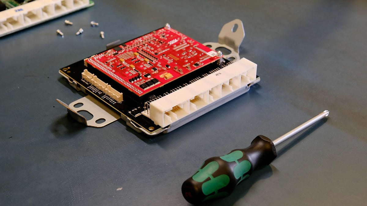
If mounting a Plug-In ECU, they are designed to make use of factory mount locations and enclosures, but before plugging in and tucking it away, read the provided manual for your ECU, many Plug-Ins have jumpers or dip switches that need to be set before install.

2. Wiring
Once the ECU install location is finalised, wiring is the next step. ECU Installs can range from no additional wiring to full custom looms, and everything inbetween. When wiring, be sure to follow best practice with powers, grounds, sensor and sensor earth wiring. Update any changes made to the wiring from the planned IO map as you go, to keep the next step of configuring your tune quick and easy.
3. Configuring Your Tune
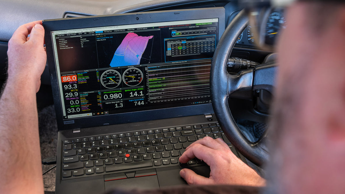
Configuring your tune is the process of inputting all relevant engine and sensor setup data into the ECU. This involves everything from telling it how many cylinders and the displacement it has, to the fuel equation you wish to use. You can do this without being connected to your ECU at first, but make sure you start with a sample map matches your ECU.
You can load sample maps from other ECUs, the tunes aren’t restricted to a given ECU (with the exception that G4x can’t open G5 tunes). Though when loading tunes from other ECU’s you need to make sure all pin assignments are correct.
It’s recommended to have the car hooked up to a battery charger as you go through calibrating sensors, plenty of time will be spent with the ignition on and the engine off during this process.
When you’re ready to go through setting everything up, we have a tech article going over many of the items you’ll need to go through, from ECU config settings, to injector setup, ignition settings and sensor calibrations.
4. Configuring Sensors
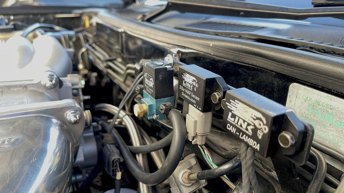
Two frequently asked questions are: Are you able to use different sensors to stock with a Plug-In? or can you use stock sensors with a Wire-In? Having a Wire-In or Plug-In does not affect which sensors are supported, if it’s supported, you can use it regardless of ECU.
As you configure sensors, you’ll need to have calibration data for that sensor. Most sensors you’ll encounter, this data is already in a drop down ready to go, but in the event there isn’t, there are custom calibration data tables you can use.
For more on this, and settings such as error voltages and pull-up resistors, all is explained in our configuring sensors article.
5. Triggering
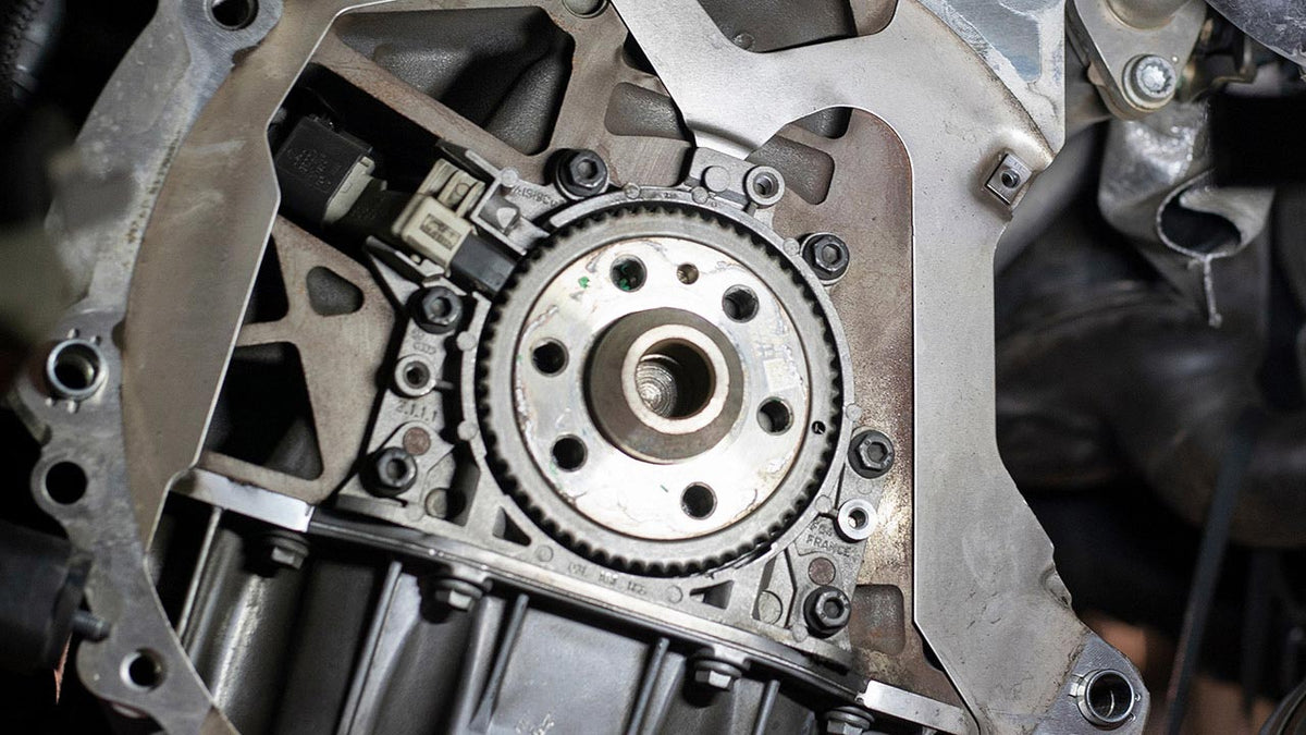
Trigger/Cam and Crank angle signals are how the ECU knows where the engine is in its cycle, allowing the ECU to know when to inject fuel and fire ignition coils.
Every electronically fuel injected car will have a trigger pattern which the sensors read to determine the engines position. There is a comprehensive list of different trigger modes already programmed inside PCLink, from Ferrari F40’s to Daihatsu Copens. If your car isn’t on the list, you can send a trigger scope to tech support who can track down what mode it should use.
There’s much more that goes into triggering, such as different styles of sensor, how the waveforms present to the ECU and so on that we explain in the triggering article.
6. Fuel Systems
There’s more to fuel systems than just fuel pumps and injectors, there are multiple ways fuel pressure is regulated, as well as return vs returnless systems for example. We talk in depth about the subject in the fuel system tech article.
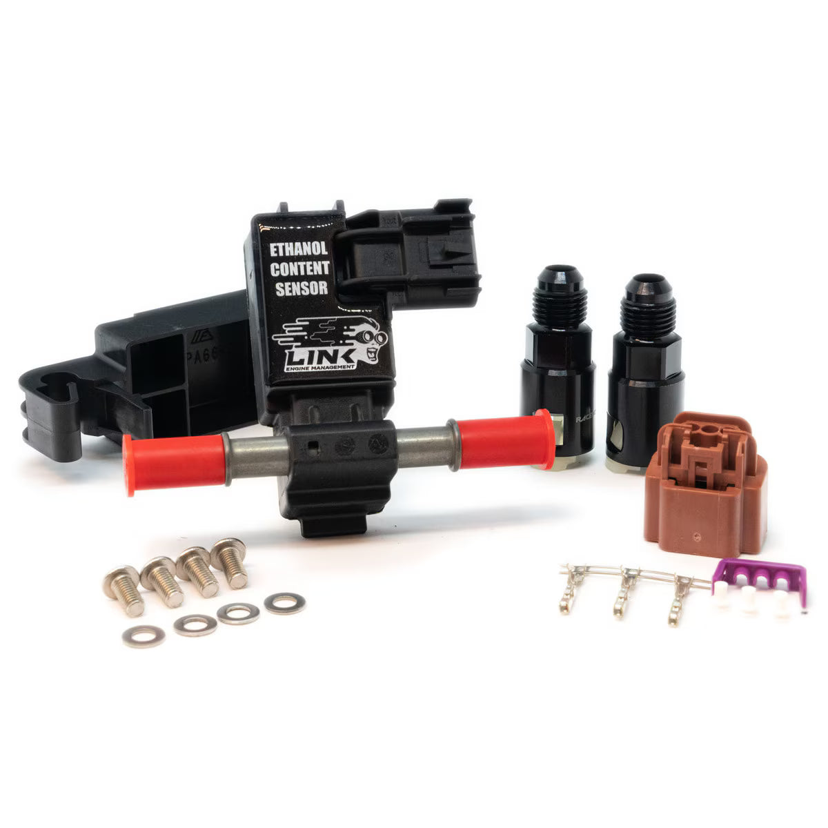
Now’s the time to set up things like the fuel equation mode, how your fuel pressure is controlled and measured, ethanol content sensors and so on.
7. Ignition Systems
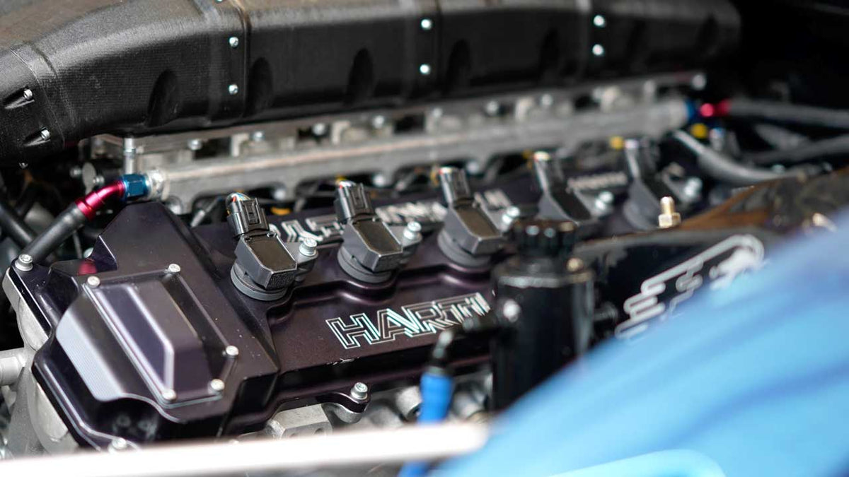
Ignition settings include items like firing order, and ignition mode like wasted spark, direct spark etc.. Configure these settings based on what’s installed and wired on the engine. Now is the time to consider things such as dwell (the time charging the coil before firing). This, likewise, is set based on the limitations of the hardware installed. We explain more in the Ignition Systems article.
8. CAN
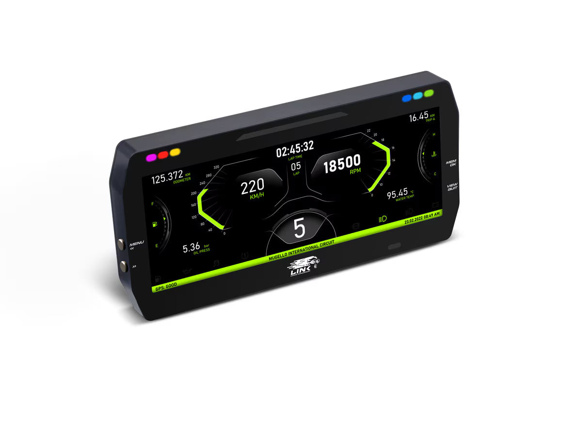
CAN (Controller Area Network) is a communications bus standard that is now ubiquitous in the automotive industry. CAN is used to communicate between different modules in a vehicle, such as the ECU, body control module, Antilock Braking System (ABS), Transmission Control Unit (TCU) and so on.
Each manufacturer defines their own specification for how they use CAN, you can think of them as the language the cars modules are speaking, and it’s up to us to tell the ECU which language it needs to be speaking in order to communcate with the rest of the car.
PCLink has many OE CAN modes available, to see the latest list of supported modes, in PCLink Help, look under ECU Tuning Functions → CAN → CAN Vehicle Modes
Link ECUs also have user defineable custom CAN which can be used for talking to various aftermarket and factory CAN devices such as the Razor PDM, or a CAN keypad for example. Most Link ECU’s have two separate CAN buses so you can both communicate to stock modules in a car, as well as adding aftermarket CAN accessories.
We get deeper into how CAN works on our support website.
9. Working to Your First Start
First Start
Once all the setup steps above have been performed, first start won’t be far off. Work through a first start checklist, such as the one found under Plug-In ECU Installation Manual in PCLink help, and you should be ready to fire up.
If things don’t go to plan, and you’re at the point where you are turning the key but the car won’t start, we have a video that runs through some of the more common issues people encounter.
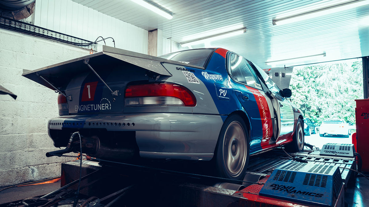
Tuning
Getting running is a major milestone. The next step is to tune it and get the most from your setup. This is where Link's established dealer and tuner network really comes in handy. Link has a huge number of dealers world wide that can help you getting your project running better than ever, or help you through those last steps getting set up. Check out the dealer map on our website, all their details are kept in one place for your convenience.